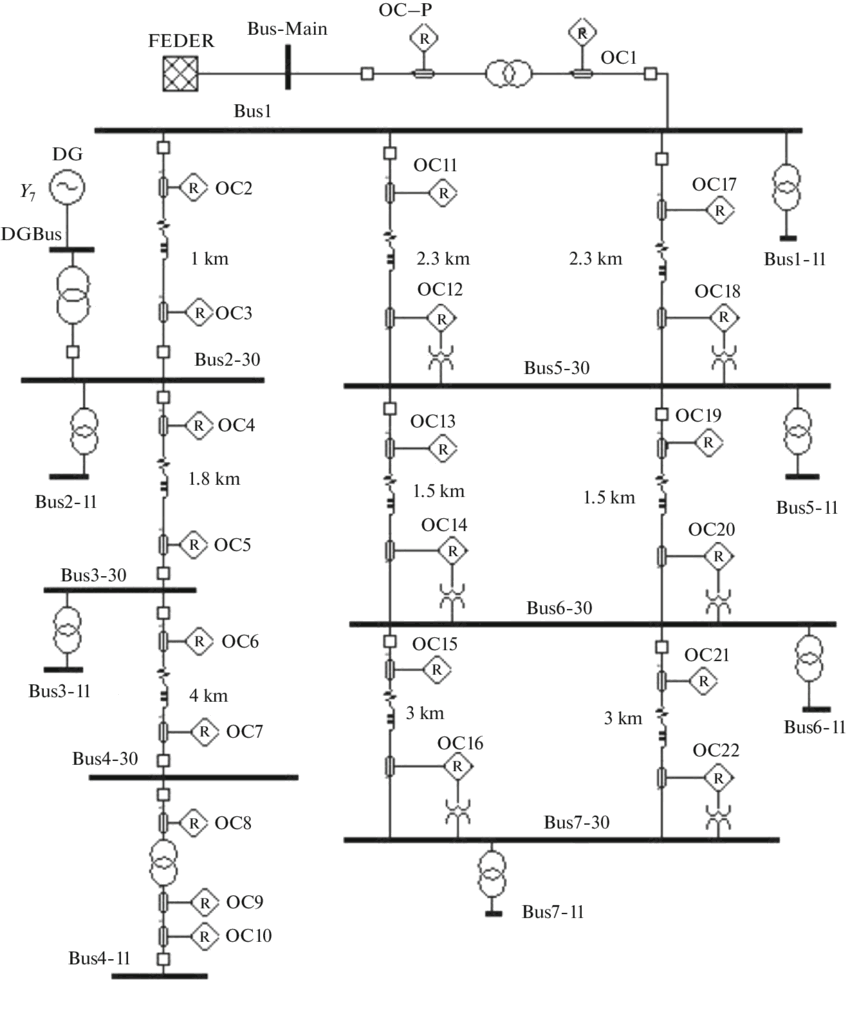
A single line diagram in electrical systems also known as One Line Diagram, it’s a simplified representation of electrical system. Single Line Diagram can be define as an Electrical diagram or drawing in which the component of electrical system are represented by symbol and describe how the electrical component are connected. In this article we will further discuss about SLD, different types of electrical diagrams, importance and benefits of SLD in electrical system.
Different types of Electrical Diagrams In the field, most preferred Electrical Drawing is ‘’Single Line Diagram’’. Even there are several other Electrical Diagrams are. Every electrical diagram used in the field of electrical engineering has its unique functions.
The types of electrical diagrams are
1. Ladder Logic Diagram
2. Wiring Diagram
3. One-Line Diagram
Ladder Logic Diagram This drawn usually like a ladder (ladder diagram because these are resemble with ladder, with two vertical lines known as rails / power supply and multiple horizontal lines known as rungs which represents control circuit). Ladder diagram is a drawing that shows the function of an electrical circuit using electrical component symbols. By using ladder diagram we can easily understand electrical system and quickly solve the electrical problems. Other names used for ladder diagram are line diagrams or elementary diagrams.
Wiring Diagram In wiring diagram electrical symbol and interconnection are used as in Ladder Diagram, only difference is that wiring diagram shows the exact location of the components. Wiring diagram is also known as connection diagram. On wiring diagram cables and components can be easily identified.
One-Line diagram SLD is a simplified way to representing a three-phase electrical system. Exact electrical connections are not shown in SLD. It’s cleared by its name, single line diagram uses one line to represent a three phase of an electrical system. A SLD is a simplified blueprint of electrical installation. Capacity, rating of electrical equipment's, circuit conductors and protection devices are clearly shown in SLD.
Single Line Diagram confines Single line diagram normally contains following information
1. Incoming / outgoing line (nominal voltage and capacity of the line)
2. Main circuit breaker, isolator, cut-outs, and bus-tie
3. Rating of power transformer, connections and earthing method used
4. Rating of feeder circuit breakers
5. Defined function, use and type of fused switches relays
6. Ratio, size and type of current and potential transformers
7. Specification of transformer used for control system
8. Size of all types of cables used
9. All information related to substation, which includes integral relays, main panel, type of load at each feeder on each substation
10. Size and critical equipment voltages of UPS, Batteries, Generator, change over switches, power distribution panel, and control room air conditioners / heaters.

Advantages of Single Line Diagram
1. Identify the schedule of troubleshooting and make it more comprehensive.
2. Single line diagram ensure the safety measure for personnel work.
3. Operation of the facilities becomes safer and reliable by using SLD.