Switchyards are critical components of electric power plants, acting as the central hub for transmitting and distributing electrical power. At the heart of every switchyard lies the bus-bar system, which plays a vital role in ensuring efficient and reliable power transfer. Bus-bar schemes are designed to accommodate various operational requirements, fault tolerance, and flexibility. In this article, we will explore the different types of bus-bar schemes used in switchyards and how they work.
What is a Bus-Bar?
- A bus-bar is a metallic strip or bar, typically made of copper or aluminum, that conducts electricity within a switchyard. It serves as a common connection point for multiple incoming and outgoing circuits, allowing power to be distributed efficiently. The design and configuration of bus-bar schemes significantly impact the reliability, safety, and flexibility of the power system.
Types of Bus-Bar Schemes
1. Single Bus-Bar Scheme
- Description: This is the simplest and most economical bus-bar configuration. It consists of a single bus-bar to which all incoming and outgoing circuits are connected.
- Working: All equipment, such as transformers, circuit breakers, and feeders, are connected to the same bus-bar. While easy to operate and maintain, this scheme has limited flexibility and reliability.
- Advantages: Low cost, simple design, and easy to operate.
- Disadvantages: A fault on the bus-bar can disrupt the entire system, and maintenance requires a complete shutdown.
2. Double Bus-Bar Scheme
- Description: This scheme features two separate bus-bars, typically referred to as the main bus and the auxiliary bus. Each circuit can be connected to either bus-bar using a bus coupler.
- Working: During normal operation, circuits are connected to the main bus. In case of maintenance or a fault, the load can be transferred to the auxiliary bus without interrupting the power supply.
- Advantages: Increased reliability and flexibility; maintenance can be performed without a complete shutdown.
- Disadvantages: Higher cost and complexity compared to the single bus-bar scheme.
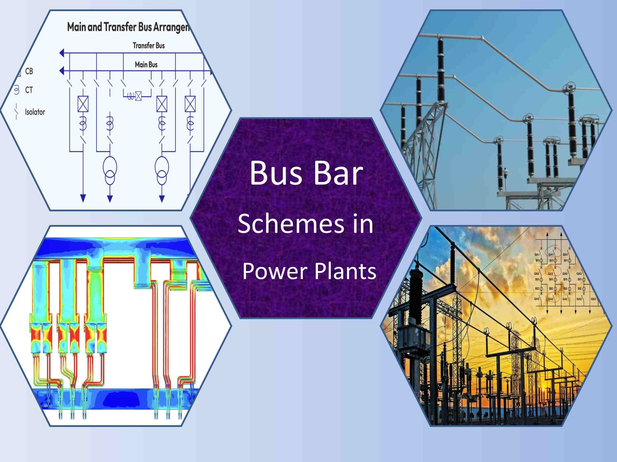
3. Main and Transfer Bus Scheme
- Description: This scheme is a variation of the double bus-bar system, where one bus-bar acts as the main bus, and the other serves as a transfer bus.
- Working: Under normal conditions, all circuits are connected to the main bus. In case of a fault or maintenance, the load is transferred to the transfer bus using a bus coupler.
- Advantages: Improved reliability and flexibility at a lower cost than a full double bus-bar system.
- Disadvantages: Requires additional equipment like bus couplers and isolators.
4. Ring Bus Scheme
- Description: In this scheme, the bus-bar is arranged in a closed loop or ring, with each circuit connected between two breakers.
- Working: Power flows in a circular path, and each section of the ring can be isolated for maintenance without affecting the rest of the system.
- Advantages: High reliability and flexibility; faults can be isolated without disrupting the entire system.
- Disadvantages: Complex design and higher cost due to additional circuit breakers.
5. Breaker-and-a-Half Scheme
- Description: This advanced scheme uses three circuit breakers for two circuits, providing a high level of reliability and flexibility.
- Working: Each circuit is connected to two breakers, and the third breaker acts as a tie between the two circuits. This allows any breaker to be taken out of service without interrupting power flow.
- Advantages: Extremely reliable and flexible; ideal for large power plants and substations.
- Disadvantages: High cost and complexity due to the large number of breakers and associated equipment.
Factors Influencing Bus-Bar Scheme Selection
The choice of bus-bar scheme depends on several factors, including:
- System Reliability: How critical is uninterrupted power supply?
- Flexibility: Is there a need for frequent maintenance or reconfiguration?
- Cost: What is the budget for the switchyard design?
- Fault Tolerance: How quickly can faults be isolated and repaired?
- Future Expansion: Will the system need to accommodate additional circuits in the future?
Conclusion:
Bus-bar schemes are the backbone of switchyards in electric power plants, ensuring efficient and reliable power distribution. From the simple single bus-bar scheme to the highly reliable breaker-and-a-half configuration, each type has its unique advantages and limitations. The choice of bus-bar scheme depends on the specific requirements of the power plant, including reliability, flexibility, and cost considerations. By understanding the different types of bus-bar schemes and their working principles, engineers and operators can design switchyards that meet the demands of modern power systems while ensuring safety and reliability.
Author Name: Engr. M. Arshad
Contact: engrarshad8@gmail.com
Comments